In a previous blog, we outlined the components of a linear edger system and their intended purpose. Now, we’ll take a look at the alignment and calibration of your linear edger.
To refresh, a linear edger operates under the basic principle that we can scan a piece of lumber while it is in one location and then ‘edge’ it when it reaches another, without handling it in between, by accurately predicting where it is going to be throughout the process.
Based on experience, this is what we have found to be the best methods for alignment and calibration.
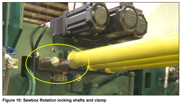
In order for the saw motion and angle calculations to be correct, the saw arbor must be perfectly square to the centerline when the sawbox is set at zero degrees of rotation. McDonough edgers are shipped with shafts and a machine locking clamp to ensure that the sawbox is set exactly at zero degrees. The holes for these shafts are bored into the sawbox simultaneous with the boring operation for the arbor bearings and are located with as little variation as possible, ensuring accurate sawbox angle calibration capabilities later on.
- When placing machinery in a linear edger system, start with the sawbox itself, physically placing it as close as possible with the desired system centerline
- After it has been placed close to what is believed to be its final resting place, always level the edger at the desired elevation for the engineered “top of roll”.
- Use a machinists level along the top of the arbor, with sawbox door tightly closed, to establish level from side to side
- When checking level across the edgers, use a quality carpenters level for long sections, and place a machinists level on top of that.
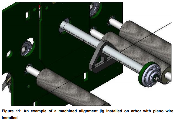
- A tight piano wire is recommended. Stretch the wire between two alignment jigs that are at a height so that it is between 1” and 2” over the desired ‘top of roll’ height at the sawbox location – it may sag slightly so set your wire accordingly
- Once the wire or laser is in place, start at the arbor of the sawbox and work out in both directions. When centering a machine measure from the piano wire (at infeed and outfeed ends of machine) to dowl pin references in sidewalls. Now you can establish feed rolls and arbor, 'true' parallel and perpendicular to piano wire.
- Once the final position of the edger has been set, finer adjustments should be made by adjusting the ends of the piano wire to bring the centerline perpendiciular to the arbor, rather than the other way around
- Being sure that the arbor is perpendicular to the machine centerline with the sawbox locked at zero degrees is critical
- Using the ‘swinging the arbor’ method, mount a square or similar device to the arbor, swinging it through to an arc so that it touches the wire both upstream and downstream
- It is critical to ensure that the sawbox is level at its desired elevation before you move it into its position of final alignment. Failure to do so will result in the need to repeat this operation. Tacking down the feet can help keep it from moving during placement of other adjacent machinery.
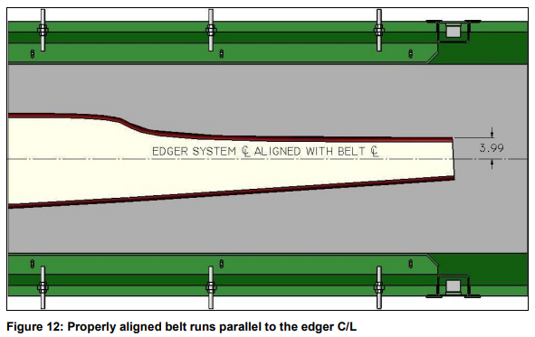
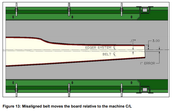
- Depending on the scanning configuration of the edger system, there may be two or more infeed belts and all need to be placed as close as possible to a position that puts their centerline exactly parallel to the now established centerline of the sawbox.
McDonough infeed belts are set up and tracked in our shop before shipment to your mill. The belt should arrive with the centerline marked on it already to ensure it is properly placed and to avoid the need to try and move the belt around after the legs have been welded down.
- Belt elevations should be established according to the height of the top of roll in the edger sawbox. The most accurate way to do this is by using a surveyor/builder transit.
- The top of the belt needs to be perfectly level from side to side and set at an elevation that it exactly the same as the edger feed rolls along its entire length
- Starting at the edger, work you way out to the ends of each belt and rollcase until the entire line is completely level to the edger bottom rolls.
- Use the transit to set the elevation at each individual foot location, working your way along the length and setting both sides before moving farther out from the edger.
- Once all elevations are set, use a machinists level to fine tune the belt level from side to side. It is also advisable to use a long carpenter’s level to ensure the transition between all belts and rolls is perfectly level across the full width.
- A quick check for correct belt elevation is to slide the 8’ carpenters level into the mouth of the edger and it should just touch the top of the bottom feed rolls without ‘bumping’ up onto the roll or having any clearance over it.
Belt Tracking
- McDonough has produced a detailed belt alignment procedure based on recommendations from our suppliers, the design of our belt systems and our experience from the field (download link)
- Once the belt is powered and you are able to run it for testing it is advisable to mark the belt center at the tail end of the conveyor on a piece of tape with a sharp marker, then jog the motor so that your piece of tape and mark will move along the belts length and can be observed relative to the centerline using a speed square.
The important of roll squareness cannot be stressed enough when it comes to belt alignment. Making sure your infeed belt is actually tight enough is also a critical factor
Saw Position
- With the servo axis properly controlled and the saws loaded in the machine you should start by measuring and entering a value into the servo ‘actual’ position within the PLC that matches the saws position relative to the machine centerline
- This value can be entered directly into the PLC on the servo calibration screen of the HMI.
- After making sure that the machine is properly locked out and there is no stored energy inside the machine, measure the distance from the center of each saw to the machine centerline. This measured value is a rough starting point for each saw position and will be finetuned later on.
- In order for the saw to cut each board along the intended path, the saw must not only be in the right location but it must also start its move along the arbor at exactly the right time. In order to properly set the saw position, remove one of these two variables (timing and position) while we calibrate the other.
- By forcing the sawbox to cut a solution with a skew angle of zero degrees we can eliminate the timing variable as the saws will simply preset and then remain still while the board passes through the sawbox.
Saw Gearing
- When the board enters the edger to be sawn, we have to move the saws along the cut path as the board passes underneath the arbor – called ‘gearing’ or ‘camming’.
- The PLC calculates how fast the saw must move, and if the encoder speeds up or slows down, then the saws will still cut the correct path as planned by the optimizer.
- We know that the saws cannot instantly accelerate to speed and so there must be a distance ahead of the board when the saws are accelerating and getting onto the planned path.
- Depending on the speed that we are feeding boards into the machine this distance might be anywhere from 8”-24” in front of the piece to be sawn.
- The timing for the start of this saw motion is critical as the saw will end up ahead of the planned cut path if the saw starts moving too early and behind the planned cut path if the saw starts moving too late.
If you have saws that are cutting on the correct path when the sawbox angle is set to zero degrees but then always seem to be out of place once you allow angled solutions, then your saw gearing timing requires calibration.
- It is highly recommended that you do not make changes to these timing points without consulting your McDonough engineer or project manager prior to doing so.
Following all of the steps above should ensure that your linear edger is functioning properly and cutting good lumber in accordance with your optimizer. If you are noticing lumber that doesn’t look right coming out of your linear edger, view our complete linear edger guide for step-by-step instructions for saw calibration relative to the machine centerline.