McDonough's white paper on ‘Maximizing performance of Linear Edger Systems’, written by VP Operations Hugh Hawley over 10 years ago, has become an incredibly popular document for customers and competitors alike on how to achieve optimal linear edger performance. Today we will examine the components of a linear edger system and their overall contribution to the performance of your linear edger. In the next blog post, we will examine alignment and calibration.
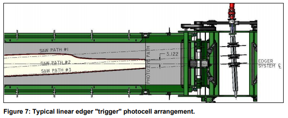
A linear edger operates under the basic principle that we can scan a piece of lumber while it is in one location and then ‘edge’ it when it reaches another, without handling it in between, by accurately predicting where it is going to be throughout the process.
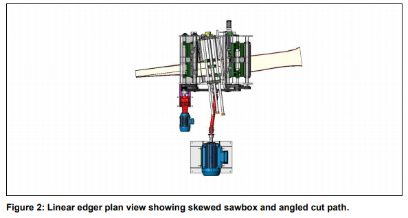
A linear edger is designed to move a piece through a scanning system along a known reference line, then saw the piece immediately afterward and before the piece is handled or moved relative to that center line. Edger systems that ‘grab’ and ‘place’ flitches after they have been scanned have introduced a number of opportunities for error before the piece ever reaches the saw itself.
- Was the board exactly where it was supposed to be when we grabbed it?
- Did we grab it where we were supposed to?
- Did we place it where we were supposed to?
- Did it slide around when we placed it on the infeed mechanism?
- Did we physically damage or modify the board during placement?
A linear edger system eliminates all that potential error. By scanning the board as it sits on the belt, intermediate handling is eliminated, and the sources of errors are reduced to our ability to predict the exact location of the planned cut path as the board passes through the edger and our ability to place a saw exactly along that path.
As each board is scanned while it passes longitudinally through the scanners, the scanning window is much smaller and requires only a fraction of the scanning hardware that would be required for a typical transverse system, resulting in simplicity and cost efficiency.
McDonough’s newest linear edger system combines the compactness of a transverse edger system with the accuracy, performance and simplicity of a linear edger system. A multi-line scanning system, fast optimization times and electric servos, as well as a simpler mechanical design have allowed us to fit our OptiFit linear edger system in the footprint where a typical manual board edger would sit in most mills.
As piece counts increase, the advantages of linear edger system over a transverse system only grow. As board placement becomes harder and harder with increased speeds, accelerations and decelerations, accuracy begins to suffer and mechanical systems start to break down, resulting in a decrease in yield.
The perceived difficulty of a linear edger system making it more difficult to properly measure, tune and maintain performance can be fairly easily managed by mill staff if they have the proper tools and training to perform regular checks on the system. In addition, irregularities with a linear edger system’s cutting accuracy are typically much easier to troubleshoot.
Components of a Linear Edger System:
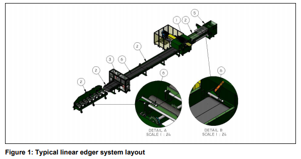
- Edging device with at least two cutting tools (the saw)
- The heart of the edger system and the machine that will remove the wood fiber designated for removal by the optimizing system. The machine must be capable of doing so very accurately at the optimum angle as established by the optimizer.
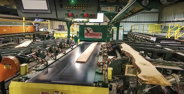
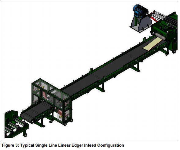
- Lumber transport system (the belts, rolls or chains)
- The most common lumber transport method seen today is a high-quality conveyer belt, also known as an infeed belt. These belts are preceded by a rollcase section where boards are scanned and loaded and fed onto the end of the scanning/infeed belt. Downstream of the edger is an outfeed belt, designed to ensure the leading end of a board that is being sawn continues to travel parallel with the established reference line.
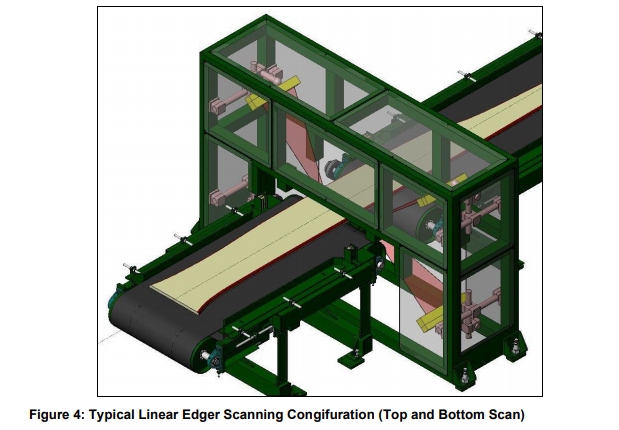
- Scanning system and optimizer (created the sawing solution)
- Used to capture an accurate image of boards as they pass through a scanning window while traveling down a conveyer. Once a good image has been captured and the optimization has modeled the piece, the optimizer will fit onto that model the combination of saw cuts that will return the greatest value of finished lumber. Recent developments in edger optimization include the use of vision technology to also take visual defects into consideration.
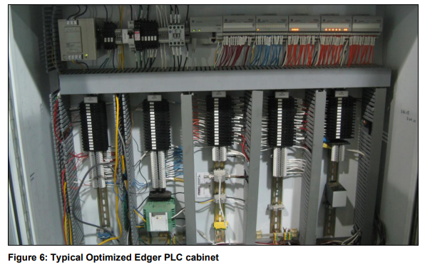
- Control system (executes the solution by controlling machinery)
- What controls all of the moving parts of the machinery by following a program of logical commands that is stored in the PLC (Programmable Logic Controller). Based on gathered inputs, the PLC can cause different actions and the controller must be capable of handling tremendous amounts of input and output data simultaneously. The scan time needs to be short enough that there will not be changes in the operating conditions significant enough to sabotage the system performance between two consecutive scans.
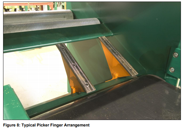
- Edging separation device (separates the board(s) from the edgings)
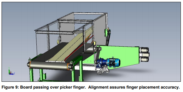
- Designed to separate finished boards from edgings, the widely accepted method for this is to ‘pick’ the good boards off of the outfeed belt with a picker finger located at the end of the outfeed belt, allowing edgings to pass and fall into the waste system below. Servo motion of the picker finger is now commonly used to keep the picker finger hidden under the board as it passes over the outfeed to avoid picking up the edgings. Recent developments allowing the picker finger to be placed very close to the sawbox has increased picking finger accuracy in thinner stock.
- Critical to any linear edger system, machine alignment refers to the alignment of all the different machinery components of the linear edger system including the infeed, transport system, scanning device, edger and separation device. The critical assumption is that the board moves parallel to the established reference line and all cutting tools are properly calibrated to move relative to that line. The picker finger is also placed under each board relative to the machine centerline, making it critical that the outfeed belt continues to track parallel to the machine centerline. Machine alignment (not a physical device but a critical component)
Some of the more common pieces of additional equipment for edgers that are not required but are often incorporated into the system are:
- Operator interface (consoles, touch screens, pedals, etc.)
- Lumber singulation and loading systems
- Solution display systems (McDonough’s ValueMax laser system)
- Thickness sizing machinery
In the next blog post, we will examine the alignment and calibration of a Linear Edger System. In the meantime, please refer to Hugh Hawley’s white paper for a full comprehensive look at maintaining your linear edger system.